
CryoPan vacuum insulation
Technology
The CryoPan hexagonal vacuum panel, how panels are welded into vacuum structures and fixed to the tank, and how the vacuum is managed and monitored.
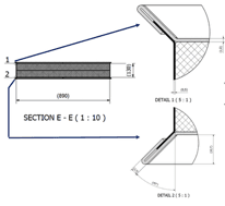
CryoVac insulation panel – CryoPan
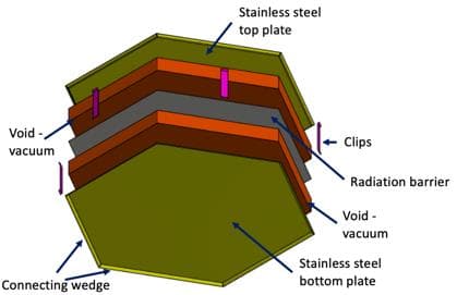
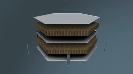
- Hexagonal shaped panel – providing structural flexibility
- Divided in two identical sections separated by a radiation barrier (details are simplified in the animated introduction)
- A top and bottom plate defines the shape and size of the panel
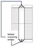
- The plates are equipped with a connecting wedge
- Top and bottom plates including connecting wedges as well as clips are all made from stainless steel
- Note – the CryoPan is open, i.e. no vacuum possible
Panels connected to form vacuum structures
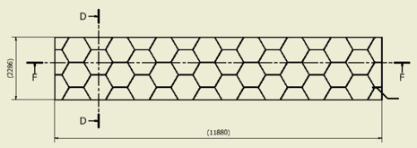
A number of hexagonal panels are welded together, connecting wedge against connecting wedge on both sides, forming a structure capable of absorbing movement.
A standard structure for a 15,000 m³ tank consists of:
- 28 standard hexagonal panels (standard panel size 0.723 m²)
- 14 adjusted trapezoid panels
- 4 adjusted pentagon panels
- 2 adjusted square panels
The standard section totals 27.2 m² and is shown in the figures.
Structure assembly and attachment
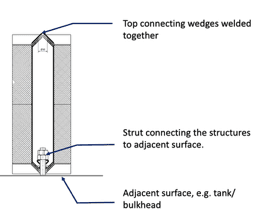
- Connecting wedges provide flexibility and movement
- Panels are welded together using the connecting wedge to form structures
- Structures are fixed to the surface applying a stud arrangement
- All steel structures in the panel share the same coefficient of thermal expansion, eliminating thermal stresses
Vacuum management and monitoring
Vacuum is applied to the individual structures and to the internal void between the tank surface and the insulation structure. Each structure connects to the vacuum management system via piping; to reduce piping, structures are grouped onto a common manifold feeding the vacuum control and management system.
Leakage evacuation system
- The vacuum management system also functions as a leakage control and collection system
- Capacity requirement for IMO type B: 200 l/hour
- Collection points erected (gas)
- Collection points, tank well arrangement
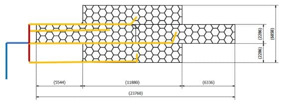
- Red:
- Manifold connecting a group of structures.
- Blue:
- Connecting pipeline – Vacuum Control System.
- Orange:
- Connecting pipeline – structures to manifold.
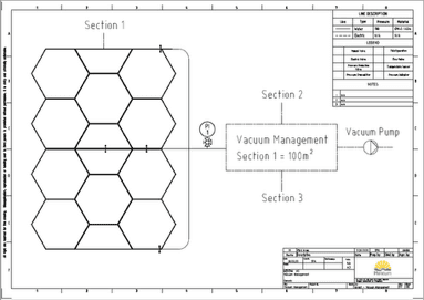
System and panel renders
Partner with CryoVac
Foundational technology value exists. The right partner can now help convert it into qualified, industrial and commercial value.