Conventional
double-wall vacuum sphere
- Full structural outer shell
- Large vacuum annulus
- Inter-shell supports
The outer shell resists external atmospheric pressure under vacuum, so buckling and stiffness govern it.

Prismatic and spherical LH2 containment
The CryoVac architecture applied to a prismatic LH2 carrier, and its extension to spherical, Moss-type LH2 tanks.
The established CryoVac architecture at prismatic LH2 carrier scale.
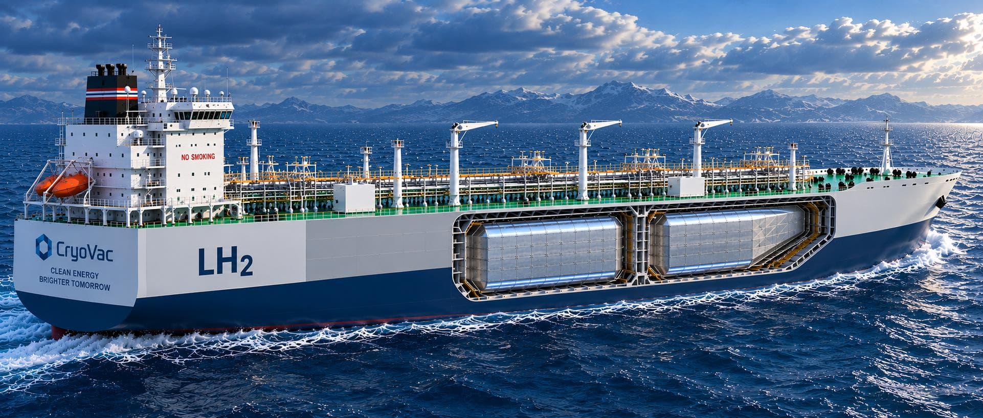
The built arrangement the CryoVac system would be applied to: primary tank, hold, inner hull and double-hull structure.
Where the dual CryoVac system would be applied
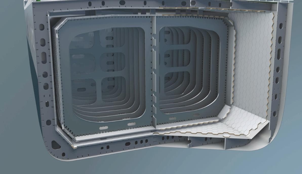
Two identical CryoVac panel systems facing each other across the interbarrier space.
Both CryoVac layers are the same panel technology, differing only in what they are fixed to.
The inner layer follows the tank geometry, the outer layer follows the inner hull, knuckles included.
The inner hull is the welded structural boundary of the double hull, not a separate wall.
Applying CryoVac vacuum-insulation principles to spherical LH2 containment, building on established Moss-type tank architecture.
Open cross-section · Moss-type arrangement (indicative)
Dashed circle indicates the conventional full outer structural vacuum sphere the concept potentially eliminates
1. Primary LH2 containment sphere
Cryogenic aluminium alloy or other qualified LH2-compatible material
2. CryoVac modular vacuum-insulation envelope
3. Moss-type support / hull integration
Established skirt-support principle – CryoVac/LH2 interface to be developed
4. Conventional steel tank shield and inerted hold
The same primary containment volume, reached two ways.
double-wall vacuum sphere
The outer shell resists external atmospheric pressure under vacuum, so buckling and stiffness govern it.
single primary sphere + panel envelope
Conventional above-deck shield and hold integration retained as required.
Potential value driver: elimination of the full structural outer vacuum sphere.
Architectural comparison only. No mass or cost benchmark has been established.
Quantitative mass benchmark to be developed
From modular CryoPan panels to a continuous spherical vacuum-insulation envelope
Spherical CryoVac envelope
Stainless CryoPan panels
forming a continuous vacuum envelope
Predominantly hexagonal panels with pentagonal transitions where the spherical geometry requires them. Panel geometry and tessellation to be developed during detailed design.
Stainless plates and a radiation barrier enclosing two evacuated voids, joined by welded connecting wedges.
Panels grouped on a common manifold. A local section can be isolated and monitored while neighbouring panels stay in service.
Structural load path and potential heat-flow path where the skirt crosses the insulation envelope.
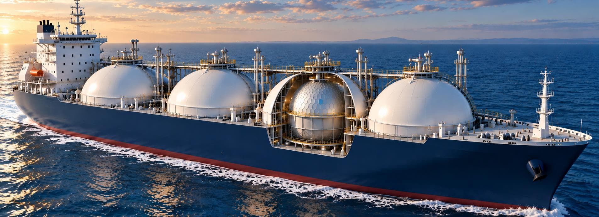
A potential four-tank LH2 carrier combining established Moss-type vessel architecture with CryoVac modular vacuum insulation.
Foundational technology value exists. The right partner can now help convert it into qualified, industrial and commercial value.