
Skip to content

Benchmarking and thermal analysis

Performance

How CryoPan compares with conventional insulation, and the thermal design basis and analysis behind the LH2 reference case.

CryoPan in comparison

Benchmark case — conventional PU insulation vs CryoPan / CryoVac, LNG reference vessel

  • 23% reduction

    Weight

  • 57% reduction

    Insulation volume

  • 57% reduction

    Installation time

  • 30% reduction

    Panel cost

  • Weight (kg/m³)

    Reference (45,000 m³)
    26
    CryoPan / CryoVac
    20

    23% weight reduction

  • Volume

    Reference (45,000 m³)
    350 mm x area
    CryoPan / CryoVac
    150 mm x area

    57% less insulation volume

  • Installation time (hours/ m²)

    Reference (45,000 m³)
    7.9
    CryoPan / CryoVac
    3.4

    57% reduced installation time

  • Panel cost (USD/ m²)

    Reference (45,000 m³)
    286
    CryoPan / CryoVac
    200

    30% panel cost reduction

  • Note 1: Insulation on tank (IMO type B) versus insulation on hull (IMO type A) reduces the insulating area by an estimated 15%, reducing CryoPan / CryoVac material costs by a further 15%.
  • Note 2: The comparison is based on a single insulation layer, for LNG applications.
  • Note 3: Reduced insulation volume improves cargo utilization of the vessel — estimated at approximately 5.4% for the reference case.
  • Note 4: PU cannot be used in LH2 applications. PU structures enclose gas in the cell structure; as the gas expands the cells are compromised. The panels are also not airtight, so condensation of N2 will occur.

CryoVac key features

Benchmarked against conventional cryogenic containment systems using a 45,000 m³ carrier as reference, the CryoVac containment system delivers:

Installation time and cost significantly reduced
Due to reduced workload
Cost of insulation system significantly reduced
Due to reduced panel costs
Reduced weight
Due to light materials and vacuum
Redundancy and safety
Unique double, separate insulation systems with easy access for monitoring
Optimized volume utilization
Space more efficiently used due to tank design (IMO type A / B versus C tank)
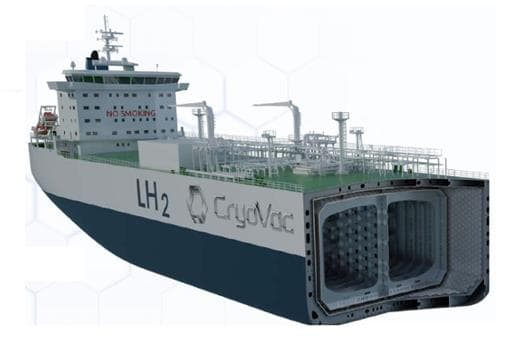
Render of the CryoVac LH₂ carrier with the hull cut open to show the two prismatic tank holds

Thermal performance & benchmarking

Thermal analysis and benchmarking executed — LH2 reference case

  • 5.2 W/m²

    Average heat leak, CryoVac structure

  • 101,475 W

    Total heat loss, 13,900 m² tank + supports

  • 27,249 W

    Margin vs 0.5% boil-off allowance

  • 5,800 kg / 24 h

    Equivalent LH2 boil-off margin per 24 h

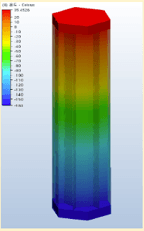
  • Air + Cardboard

    Temperature (℃) – Warm side
    45
    Temperature (℃) – Cold side
    -163
    Air
    Fluid
    Material(air) Environment
    1.013 bar
    T/C of Air (W/mK)
    0.02563
    Area (cm²)
    6.55685
    Heat flux(W)
    0.0327734
    Q (W/m²)
    49.983
    Warm side surface temp.(℃)
    35.4526
    Temperature plot, Air + Cardboard
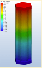
  • Vacuum + Cardboard

    Temperature (℃) – Warm side
    45
    Temperature (℃) – Cold side
    -163
    Air
    Fluid
    Material(air) Environment
    0.005bar
    T/C of Air (W/mK)
    0.003
    Area (cm²)
    6.55685
    Heat flux(W)
    0.00650374
    Q (W/m²)
    9.919
    Warm side surface temp.(℃)
    42.9969
    Temperature plot, Vacuum + Cardboard
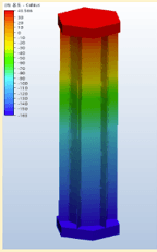
  • Absolute vacuum + Cardboard

    Temperature (℃) – Warm side
    45
    Temperature (℃) – Cold side
    -163
    Air
    x
    Material(air) Environment
    x
    T/C of Air (W/mK)
    x
    Area (cm²)
    6.55685
    Heat flux(W)
    0.001936
    Q (W/m²)
    2.953
    Warm side surface temp.(℃)
    43.566
    Temperature plot, Absolute vacuum + Cardboard
FEA thermal analysis of the CryoVac structure. Calculations exclude the effect of the radiation barrier.

For the benchmarked LH2 carrier case, conventional PU insulation does not meet the required thermal-performance target, while the CryoVac structure clears the 0.5% boil-off criterion with a 27,249 W margin.

Boil-off can be tuned by reconfiguring insulation thickness — vacuum zone sized at 2 x 200 mm for the reference case.

Thermal design basis – why vacuum matters at LH2

At LH2 temperature difference the required insulation performance moves beyond practical conventional thickness.

Insulation thickness required to meet the 0.5% boil-off criterion
Conventional PU insulation
≈ 1.39 m
CryoVac panel vacuum zonetwo vacuum zones of approximately 200 mm, 400 mm total
2 × 200 mm

Both bars to the same thickness scale. This is the panel vacuum zone; the interbarrier space between the two panel systems is a separate dimension.

Conventional insulation cannot reach the required performance within a practical hold thickness.

  • 0.01792

    W/m²K

    Required U-value at the 0.5% boil-off criterion

  • +43%

    temperature difference

    Effect of LH2 against the LNG reference duty

  • ≈ 29,299

    W

    Supports, foundations and domes at LH2 conditions

Reference case: 13,900 m² tank surface, LH2 at −253 °C, 90% filling. Vacuum insulation is the route that fits the required performance into the available thickness.

Thermal analysis & verification

What has been analysed, and what is carried forward as the LH2 reference evaluation.

Executed analysis

LNG conditions · approx. −163 °C
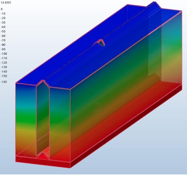
FEA temperature plot of a CryoVac panel section, cold (blue) at the top to warm (red) at the bottom
Panel FEA · Case 4
local flux, joint and stainless side wall included
82.45 W/m²
warm-face surface temperature
14.94 °C
panel core, hexagonal, absolute vacuum
0.00185 W/mK
Vacuum quality · cardboard-core cases
air, 1.013 bar
49.98 W/m²
vacuum, 0.005 bar
9.92 W/m²
absolute vacuum
2.95 W/m²

Radiation barrier excluded from these cases.

LH2 reference-case evaluation

−253 °C cold face to +45 °C warm face

141 W in −253 °C basis

141 W out

  • panel sides 70 W
  • clips 11 W
  • core 61 W
  • Panel core conductivity 0.003 W/mK at 1 mbar.
  • The radiation barrier splits the void and cuts the radiative path.
  • Stainless load paths, 11 W/mK, are kept short and thin.

Gives an average heat leak of 5.2 W/m² over 13,900 m² of tank surface, the basis of the benchmark above.

Source calculation is approximate; it excludes stainless-to-adjacent-material effects.

Vacuum-quality benchmarking and panel FEA are executed at LNG conditions; the LH2 carrier figures are a reference-case evaluation built on that analysis.

Partner with CryoVac

Foundational technology value exists. The right partner can now help convert it into qualified, industrial and commercial value.

Get in touch